~*~
Building Tinyboard: a Rust-based platform for e-ink gadget apps
It all started with a tweet
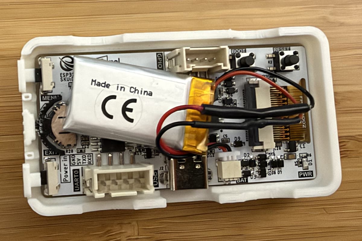
I was flying home from SF and had a few more days of vacation (the weekend) to spare, when I noticed a tweet. Steve Ruiz posted about how LLMs have completely changed the equation of real human cost for developing on cheap ESP32 e-paper boards. I've always been hardware curious, though never enough time to truly sit down and learn how. So I bought one — the Elecrow CrowPanel ESP32-S3 2.13" E-Paper HMI (model DIE01021S): a 250×122 e-paper panel, an ESP32-S3 with WiFi, 8 MB of flash, two buttons and a rotary wheel, all on one board for the price of a nice lunch.
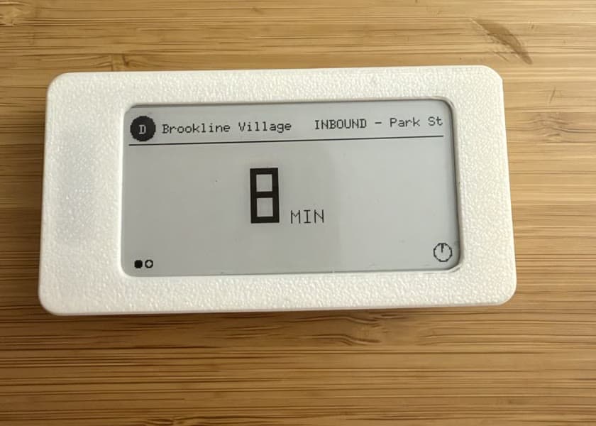
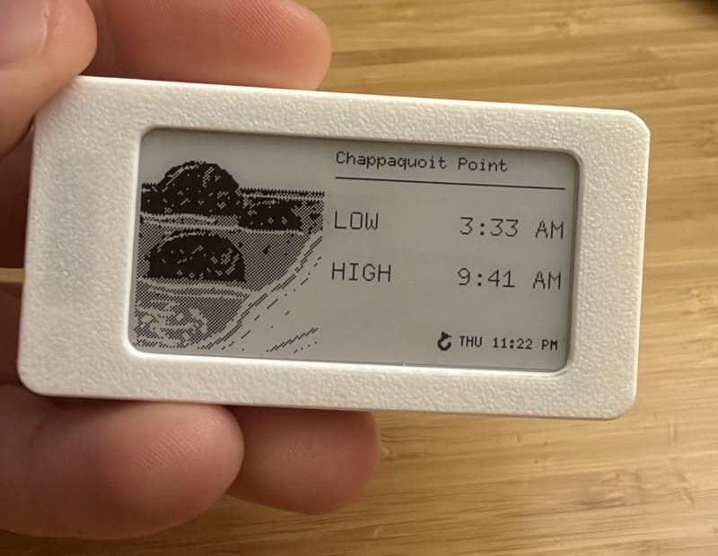
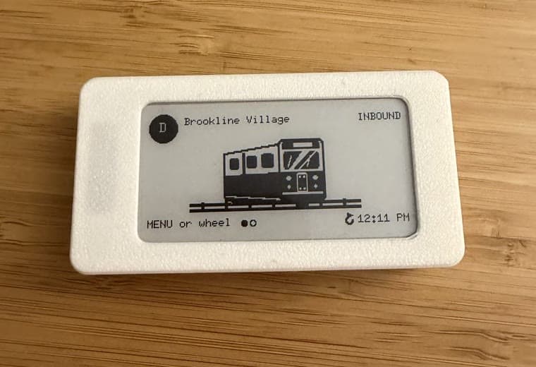
I had one silly idea: an e-ink train tracker for my wife who chooses between two train lines every morning on her commute. Then it became another similar gadget for my sister and her husband, and then one for my parents to track tides on their beach house (the beach swimming experience is much better on high tide). See the finished products above.
Then I had a few more ideas, small hand-built gifts I wanted to give my friends and family. I realized that these are all almost the same device actually and what I really should do is build a platform for producing these apps super quickly.
One gadget, two gadgets, n gadgets
Every device I wanted was the same device wearing a different shirt:
- An e-paper screen shows some information or some standby art/picture. The device sleeps at near-zero power, occasionally wakes up, turns on WiFi, fetches data, redraws the screen, and goes back to sleep.
- Each one needs a little config: which station, which tide location, what timezone, when to wake.
The train tracker and the tide tracker differ in maybe 10% of their code. The other 90%: WiFi, storage, the display driver, buttons, deep sleep, the whole configuration story are all nearly identical. So instead of one gadget I built tinyboard: a platform where the shared 90% is written once, and a new gadget is one Rust module implementing a small trait.
But before any of that could work, I had to switch brains to firmware coding, power optimization, and later 3D printing.
There is no main loop
With the radio on, this chip draws something like 100 mA. In deep sleep it draws about 10 µA. That's a factor of 10,000: one second awake costs roughly three hours of sleep.
If you want a battery to last months, the only metric that matters is seconds awake per day. And that leads somewhere I found genuinely strange as a software person: this firmware has no main loop. None. main() runs once, does one unit of work, and ends by calling esp_deep_sleep_start(), which powers down everything except the RTC. RAM is gone. The next thing that ever runs is main() again, from the top, on a fresh boot.
A boot is not startup. A boot is a wake. What makes this workable is the panel itself. E-paper is bistable: it holds its image with zero power. From the doc comment in platform/power.rs:
The display is not something to keep alive; it is the one part of the device that is already always on.
So the screen is the state that survives. RAM doesn't persist, no process persists, but the last thing an app drew stays on the glass for hours or days while the chip is off, at no cost.
When the chip does wake, power::wake_reason() reads why from the sleep controller and the whole story of a boot is captured in one enum:
pub enum Wake {
    /// Power-on, reflash, or a software restart.
    PowerOn,
    /// The deadline the app asked for came around.
    Timer,
    /// A key was pressed — somebody is standing
    /// in front of the device.
    Button,
}
And when the app is done, it doesn't loop {}. It returns a value saying when it wants to exist again:
pub enum Sleep {
    /// Come back after this long, or on a key
    /// press, whichever is sooner.
    For(Duration),
    /// Come back only when a key is pressed.
    UntilButton,
}
The platform clamps that to between 5 seconds and 24 hours, so an app that miscomputes a deadline gets a pause instead of a reboot loop. The MENU button and the wheel press are armed as wake sources through the RTC domain (esp_sleep_enable_ext1_wakeup), so the device is always responsive to a person even though it's almost never running.
One boring-sounding thing bit me immediately here: the firmware image is 1.26–1.73 MB depending on the app, and ESP-IDF's default partition table gives your app 1 MB. Even its “large” variant only gives 1500 K. By the way, you won't really see warnings, the flashing just fails in a confusing way. The fix is a custom partitions.csv handing the app 4 MB of the 8, which also buys the flash headroom that the config story below is going to spend.
   ┌─────────────────────────────┐
   │  deep sleep  ·  ~10 µA      │
┌─▶│  the panel holds its image  │
│  └──────────────┬──────────────┘
│        timer or button press
│                 ▼
│      boot: main() from the top
│                 │
│      fetch (radio on, only late)
│                 │
│        draw to the panel
│                 │
│                 ▼
└───── esp_deep_sleep_start()
A platform, not an app
The “app” part is the App trait from src/platform/app.rs: a name, its config fields, a validator, and update() — one wake's worth of work. The smallest real app in the repo, src/apps/hello.rs, is about 40 lines:
impl App for Hello {
    fn name(&self) -> &str {
        "hello"
    }

    fn config_fields(&self) -> Vec<ConfigField> {
        vec![ConfigField::text("greeting", "Greeting")
            .required()
            .default_value("hello")]
    }

    fn update(&mut self, ctx: &mut AppContext)
        -> anyhow::Result<Sleep>
    {
        let greeting = ctx
            .get_str_or("greeting", "hello")
            .to_string();
        ctx.display()
            .show_message(&greeting, &["tinyboard"])?;

        // Never calls online(), so this image never
        // powers the radio at all: it draws once and
        // the panel holds it.
        Ok(Sleep::UntilButton)
    }
}
That's the entire contract. Register the app behind a cargo feature and cargo run --release --features hello flashes it. One firmware image runs exactly one app; building with zero app features, or two, is a compile error on purpose.
Everything else lives behind AppContext, the only surface an app ever sees: config getters, a display handle, http_get(), the wake cause. The design rule I'm proudest of is small: online() is called at the point of the fetch, not at the top of update(). The radio physically stays off until an app asks, so an app that wakes and decides it has nothing to fetch never draws a milliamp of RF current. Two rules make an app power-efficient: ask for the network late, and return promptly.
Putting ink on the display
The Rust ecosystem has epd-waveshare, a driver crate for e-paper panels, so the first move was to just pull it in and point it at the screen.
Except its only 2.13" black/white module drives the older SSD1675 controller with hardcoded waveform tables, and this panel is an SSD1680. There's no SSD1680 variant in the crate, including on git master. So src/platform/epaper.rs is a minimal port (363 lines) of Elecrow's own Arduino example built (and verified) using Claude Code.
The panel's power rail is behind an enable line on GPIO7. Elecrow drives it high in their sketch's setup(), not in their display driver. If you miss it, every SPI write completes successfully and does nothing. No error, no garbage, just an empty panel.
The next problem turned out to be the most interesting one: how does a device with two buttons and no keyboard learn your WiFi password?
The gift that requires an engineering degree
These are gifts. My wife, siblings, friends, and parents shouldn't need to plug an ESP32 board into their computers, download code, and have Claude make modifications.
Naturally, I thought: we need an app! The device advertises over Bluetooth, the app pairs with it, and you configure everything from a nice native UI. I built a simple version of this but it left a lot to be desired, namely I did not want to distribute an app and require my family/friends to install it to configure it.
It then hit me: the WiFi radio can be an access point, and an HTTP server. Everyone has a web browser. The config UI should ship inside the board.
Hold MENU for three seconds and the device becomes its own network. The panel draws instructions and a scannable WiFi QR code, generated on-device in display.rs. Point a phone camera at it, join, and the phone pops the config page open on its own. We hacked the config by becoming a captive portal.
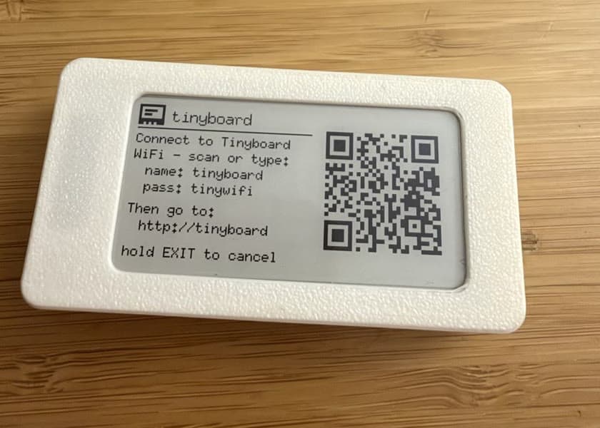
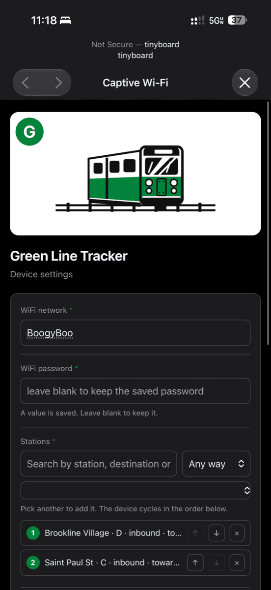
That auto-open is the captive portal trick, and it's two cooperating pieces. First, the AP's DHCP server tells every client “I am also your DNS server” (wifi.rs sets the router netif's dns address, which esp-idf-svc turns into the ESP_NETIF_DOMAIN_NAME_SERVER option). Second, a tiny DNS responder in portal.rs answers every A query, for any name, with the board's own address, 192.168.4.1:
if answers == 1 {
    // name: pointer to the question
    response.extend_from_slice(&[0xC0, 0x0C]);
    response.extend_from_slice(&TYPE_A.to_be_bytes());
    response.extend_from_slice(&CLASS_IN.to_be_bytes());
    response.extend_from_slice(&TTL.to_be_bytes());
    // RDLENGTH
    response.extend_from_slice(&4u16.to_be_bytes());
    response.extend_from_slice(&ip.octets());
}
Your phone joins a network and immediately tries to reach its connectivity-check domain to ask “is there internet here?” The board answers the DNS lookup with itself, serves a 302 instead of the expected response, and the OS goes “ah, a sign-in page” and opens it. The entire responder is a single small module that parses just the header and one question, raw bytes in, raw bytes out.
You are not a web developer here
The config pages themselves got ambitious. The tide tracker's page embeds a searchable picker over all 3,499 NOAA tide stations — with coordinates, so it can sort by distance. It has to be embedded: a phone connected to the board's AP has no internet, so search runs entirely in the browser against a catalog baked into the page. The result is a 180 KB HTML file served from a microcontroller.
I wasn't trying to be too clever, just cognizant of memory usage. The page is a template, the catalog is a string, so do the boring web-dev thing:
PORTAL_HTML.replace(CATALOG_PLACEHOLDER, catalog::PACKED)That line allocates the template, plus the catalog, plus the output: roughly 350 KB of heap on a chip with about 320 KB of usable RAM. The device didn't even get to serve a page. It aborted during boot.
The fix is to never assemble the page at all. Embedded assets live in .flash.rodata, which on the ESP32 is memory-mapped — a &'static str into flash costs flash, not RAM, but only if you never copy it. So portal_html() returns segments:
/// Segments rather than one `String` on purpose:
/// every piece stays a `&'static str` living in
/// flash, so splicing a 167 KB catalog into a
/// template costs three pointers instead of copying
/// the whole page into a heap buffer twice its size.
fn portal_html(&self) -> Vec<&'static str>
The HTTP handler writes the segments in order, 4 KB at a time, straight from flash to socket. The 180 KB page now costs three pointers of RAM, and a test asserts every segment still points into the flash-resident statics so nobody quietly reintroduces a copy.
One more keyword from the same lesson. Declare an embedded asset as const and Rust inlines it at every use site — which for the tide catalog meant two full copies in the flash image. Changing const to static cut exactly 166,960 bytes from the firmware.
Trains and tides
The train tracker rests showing fun line artwork: a trolley head-on, drawn against the panel's 250×122 viewBox. The train tracker can be configured with up to 8 stations and 3 wake times (you can always press a key to wake it). When awake, it fetches, and shows live train arrival predictions for a (configurable) 10-minute session before going back to art (sleep, don't want to show stale predictions).
The tide tracker wakes at configurable times (i.e. 7am and 10pm) and then freezes the predictions on the screen with deep sleep (tide times can be stale, they don't really change).
Waking at 7am is harder than it sounds, and it produced my two favorite small hacks in the codebase.
The chip boots thinking it's 1970 and needs the real time before it can schedule anything. The boring answer is NTP. The better one: the app is already fetching data over HTTP, and every HTTP response carries the server's clock in its Date header. http_get_bytes() in app.rs parses it (clock::parse_http_date) and sets the system clock, accurate to the second, for free. No extra round trip needed, and NTP never blocks a wake.
Then there's the drift. Deep sleep is timed by the RTC's uncalibrated RC oscillator, which drifts a few percent. A nine-hour sleep aimed at 7:00 can land at 6:48 — at which point a naive scheduler refreshes, sees 7:00 still ahead, sleeps twelve minutes, and boots again: two full wake cycles for one scheduled refresh. So clock::next_daily refuses to target any slot within a guard window:
pub const SCHEDULE_GUARD: Duration =
    Duration::from_secs(20 * 60);
With the firmware done, the board still needed a case.
Even mechanical design is just code
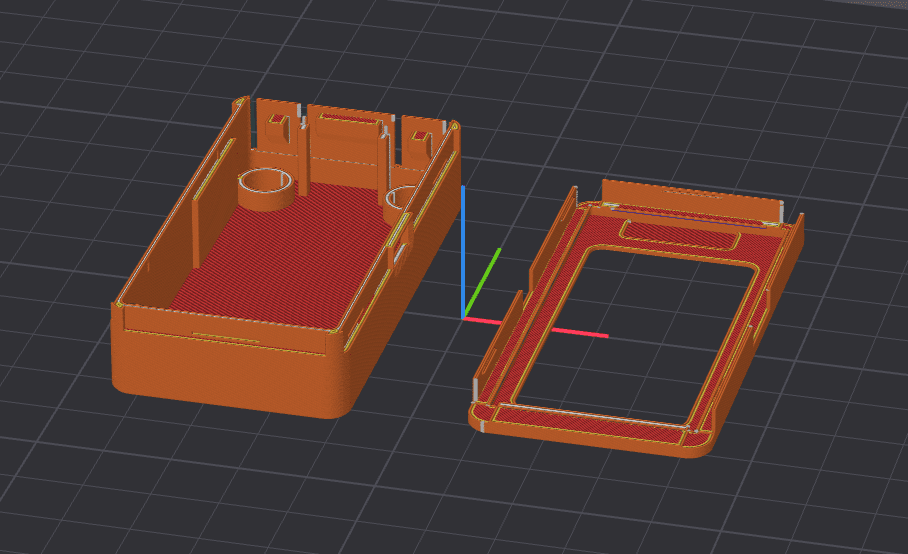
A gift needs a case: something slim that snaps together, mounts on a fridge with magnets, and still lets you press buttons through the wall. I don't own a CAD seat and I wasn't going to learn one for this. I'd started this case in OpenSCAD, and code-as-CAD was clearly right: parameters, diffs, regeneration. But OpenSCAD is terribly slow and impossible to spot check, so I moved to build123d: a Python library over a real B-rep kernel. The entire enclosure became hardware/enclosure.py, 502 lines of parameters and operations that exports STLs and a STEP. Same appeal as the firmware: the case is source code.
CLEAR = 0.30    # PCB perimeter clearance
FLOOR_Y = -13.1 # interior depth: deepest board
                # part is at -9.75, +3mm battery
WHEEL_NUB_FACE = -33.30  # wheel-press reach,
                         # gauge-calibrated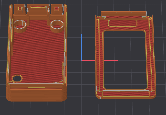
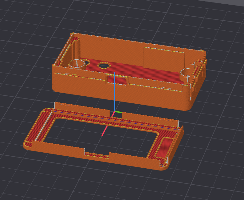
Now, to model a case around a board you need to know where everything on the board is. Elecrow publishes a STEP model of the assembly, so I imported the vendor's STEP and modeled against it.
I printed a case designed against it but the wheel flap misses, because the model places the rotary wheel about 1 mm from where it really is. It models the wrong key part entirely. It shows mounting holes that don't exist on the physical board. And it omits a resistor row that very much does exist, right where I'd put a standoff.
Luckily for me, Elecrow also ships the Eagle .brd file (the actual PCB design), the thing the factory manufactured from. Components can't be in the wrong place in the file that placed them. So parse_brd.py extracts real component positions from crowpanel.brd, and the case is modeled against those.
And when even that wasn't enough, plastic was the final step. The wheel's roller apex (the exact spot the button flap has to press) didn't match anything: the STEP said one thing, the Eagle brd file another, and the physical switch is its own device soldered on top. So testslice.py generates a calibration gauge: just the bottom slice of the case, with a three-step nub instead of the real one, each step marked with notches. So I printed it, dropped the board in, and saw which step touches the roller.
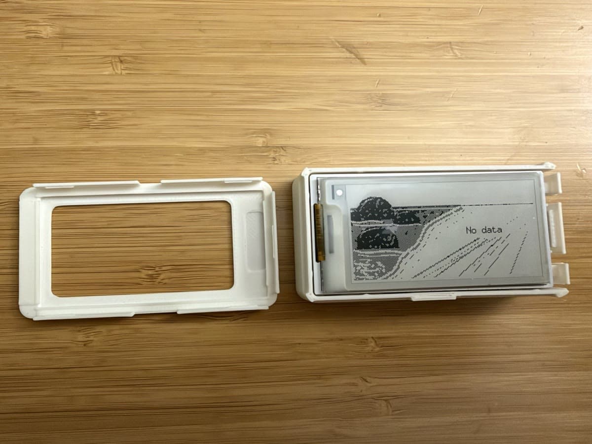
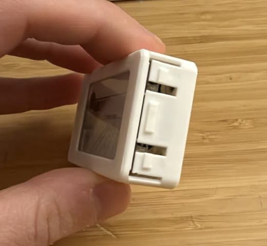
Then we built some nice CI for mechanical design, verify_final.py imports the finished STEP, intersects both case parts against every board component (with the two known-wrong STEP parts swapped for Eagle-derived stand-ins), and reports any overlapping volume plus minimum clearances:
base: total collision 0.0000 mm^3
dist base<->real-wheel
  (nub gap, expect ~0.15): 0.1500
RESULT: PASS (0 issues)
And enclosure.py runs its own asserts on every regeneration — including intersecting a virtual 6×3 mm magnet with each pocket to prove the pocket actually accepts one. Boolean geometry as unit tests. Any edit that makes the case collide with the board fails loudly before I've spent four hours printing it.
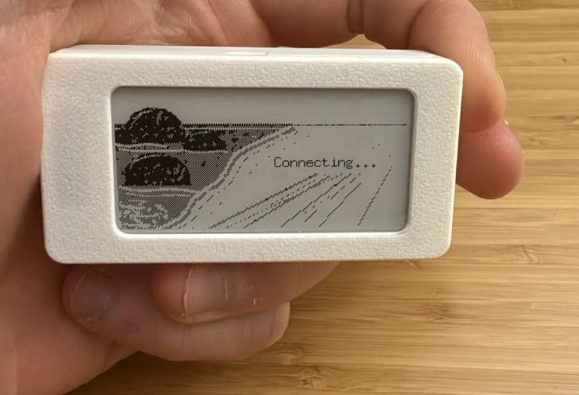
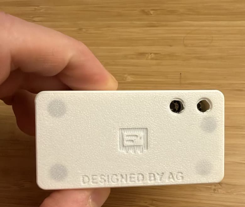
The final case is 35.8 × 69.9 × 16.7 mm: the board press-fits past tapered crush ribs (no screws, no rattle), three living-hinge flaps in the wall press MENU, the wheel, and EXIT through solid plastic, four counterbored magnet pockets sit behind a 0.4 mm membrane, there's room for a battery pouch under the board, and the bezel snaps on with five chamfered ridges. Both parts print with no supports. The back carries an engraved mark (my favorite, a little Tinyboard logo I asked Claude to design) and a signature, because why not. (Note: printing text requires some trial-and-error.)
Coding agents are a game changer for diving into the unknown
I said at the top I'm not a hardware person. Before this I knew nothing about firmware engineering (though I heard embedded Rust had some great projects), and I never 3D printed anything. Here's the honest version of how a software engineer ends up creating hardware gadgets for his family and friends (they loved them by the way).
On the firmware side, it felt like pairing with someone who had already read the ESP-IDF docs. Claude ported Elecrow's Arduino driver to esp-idf-hal, knew epd-waveshare wouldn't work and why, and chased the boot-time abort down to that .replace() call.
The enclosure was stranger because Claude can't hold a caliper or look at a print — I had to do the measuring and checking. So everything physical turned into a program: the .brd parser when the STEP was wrong, the collision checks, the printed gauge for finding the wheel. I was the hands and eyes, Claude wrote the tools.
If you're a software person eyeing that same tweet: hardware is more approachable than it looks. The annoying parts are real — an undocumented GPIO7, a 320 KB RAM limit, a vendor model that doesn't match the board — but Claude saved me weeks on them, and most of my time went into the actual product.
The tide clock is on my parents' fridge. It wakes for about 2 seconds a day, and the battery should last many months. My wife checks her trolley every morning on a screen I made her.
Not bad for a weekend project.