~*~
Tinykeys: LED Macro Pad
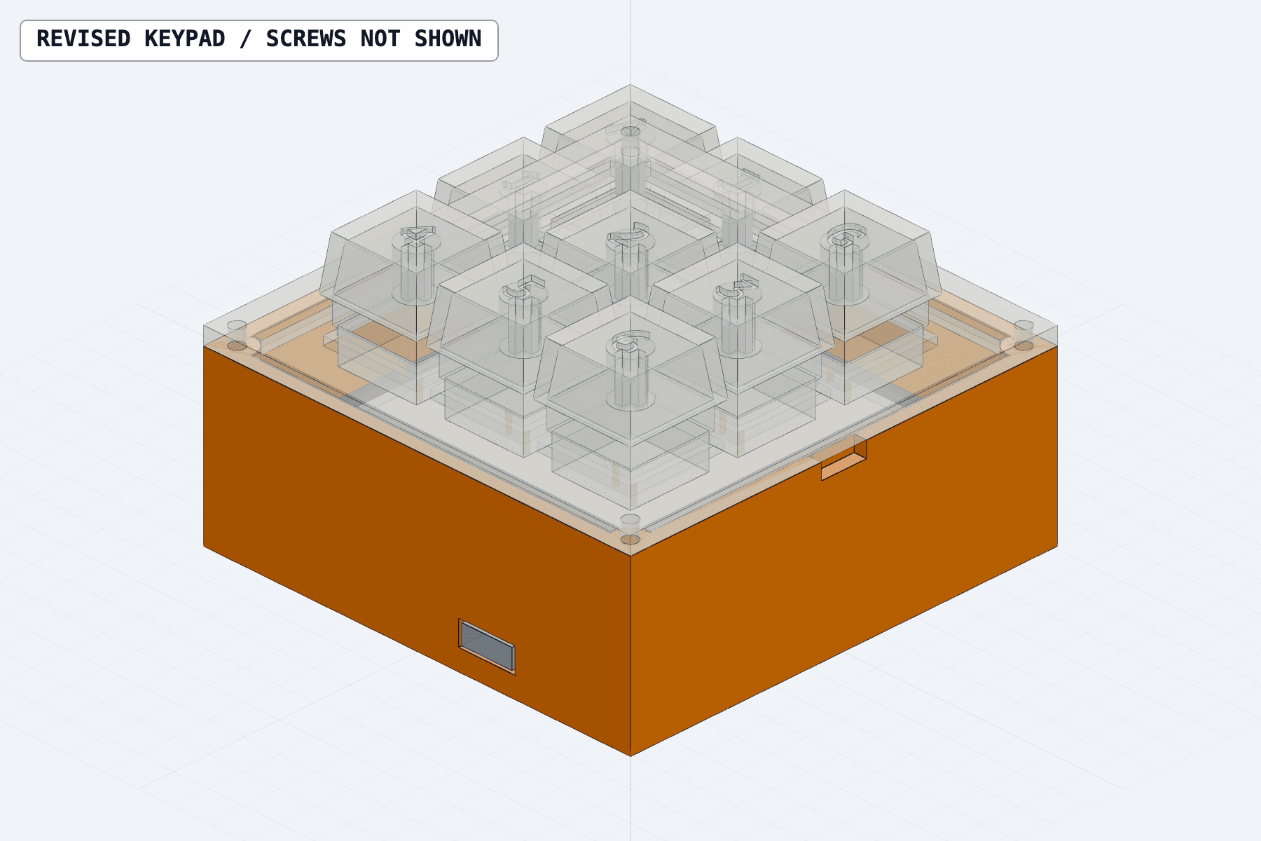
Assembly view. The four plate-to-case screws are omitted.
Tinykeys is a nine-key programmable macropad for macOS. A handwired switch matrix connects to a Seeed Studio XIAO ESP32C3; a 64-LED RGB panel illuminates the keypad; a SwiftUI companion app maps key events to shortcuts and app launches.
System specification
| Subsystem | Specification |
|---|---|
| Input | Nine clicky blue switches in a 3×3 matrix; three row buses, three column buses, one diode per switch |
| Controller | Seeed Studio XIAO ESP32C3 |
| Lighting | 64-LED RGB panel; one color across the entire panel |
| Enclosure | Printed base, removable switch plate, nine keycaps; approximately three inches square |
| Host connection | USB serial key events to a macOS companion app |
| Firmware | Arduino C++ with Adafruit NeoPixel |
| Host software | SwiftUI editor and menu bar app |
| Power | USB for the controller; separate current-limited 5 V supply for the LED panel and buffer; common ground |
The wired configuration uses no battery or gyro. The CAD reserves space for both, but portable power requires separate charging and protection circuitry.
System architecture
The controller scans and debounces the switch matrix, reports key transitions over USB serial, and drives the LED panel through a 74AHCT125 level shifter. The Mac app receives those transitions and executes the assigned action.
| Responsibility | Location |
|---|---|
| Matrix scanning and switch debounce | Controller firmware |
| Key press and release events | USB serial connection |
| Lighting response | Controller firmware and LED panel |
| Shortcut and app-launch assignments | Mac app; saved on the Mac |
| Persistent colors and brightness | Controller; written with Save LEDs to device |
Changing a key assignment does not require a firmware upload. The ESP32-C3's built-in USB peripheral does not provide a regular USB keyboard interface; host actions depend on the companion app running.
Core components
| Quantity | Component |
|---|---|
| 1 | Seeed Studio XIAO ESP32C3 |
| 9 | Clicky blue mechanical switches |
| 9 | Matrix diodes, one per switch |
| 1 | 64-LED RGB panel |
| 1 | 74AHCT125 level-shifting buffer |
| 1 each | Printed base and switch plate |
| 9 | Printed keycaps |
| 4 | Plate-to-case screws |
| As required | Matrix wire, insulation, LED data resistor, and capacitors |
| 1 each | USB cable and separate current-limited 5 V LED supply |
Mechanical design
The base, switch plate, and keycaps are parametric Python models built with build123d. Shared dimensions keep the parts aligned when the layout changes.
- The LED panel sits on supports inside the base and faces upward.
- Nine switches clip into the removable plate above the panel.
- Four screws secure the plate to the base.
- The XIAO sits at the front opening for direct USB access.
- Translucent filament in the plate and keycaps transmits the panel's light.
- PT Mono legends are recessed into the caps, leaving a thin plastic layer beneath the letters.
The reference legends are A J G / 1 2 3 / 4 5 6. Legends are independent of software assignments.
Print one test keycap and a corner test piece before the full enclosure. Verify switch fit, screw closure, and legend illumination over the panel; the switch and stem can cast shadows. Adjust fit before printing the base, plate, and nine caps.
Electrical design
Switch matrix
Each switch connects one column bus to one row bus through a diode. The diode's band faces the row. Nine diodes prevent false key detections when multiple switches are held. The controller scans one row at a time and reads the columns, using six signal lines for nine keys.
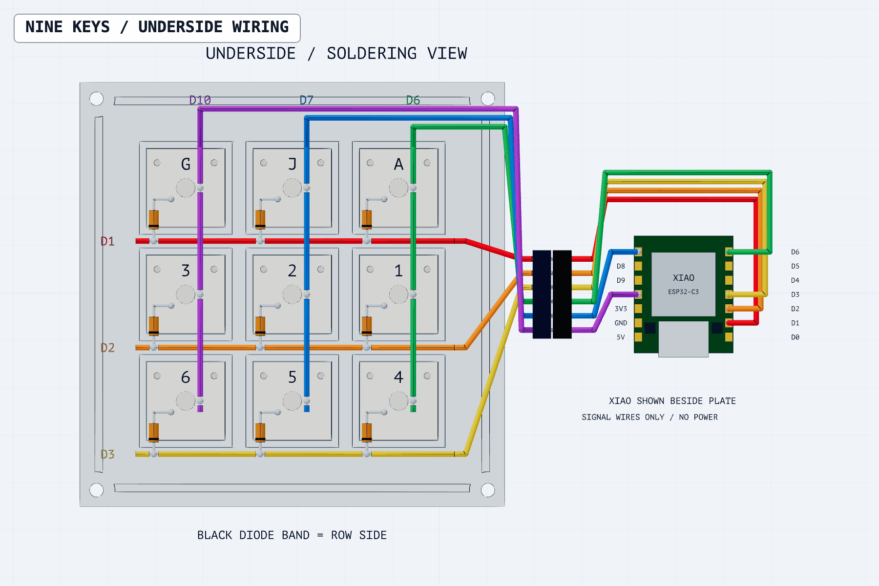
Underside view. Key positions are mirrored; board placement is illustrative and power wiring is omitted.
Seat the switches in the plate before soldering. Label all rows and columns before turning the assembly over: the top row reads G J A from underneath. Insulate wire crossings and exposed diode leads. Leave enough wire slack to remove the plate. No switch terminal connects to 5 V.
LED signal and power
The 74AHCT125 shifts the controller's data signal to the panel's logic voltage. The LED circuit includes a data resistor and capacitors. The companion firmware uses D0 for LED data. This pin also affects boot behavior; verify its pull-up configuration and reliable startup after reset.
| Connection | Requirement |
|---|---|
| Controller supply | USB |
| Panel and buffer supply | Separate, current-limited 5 V source |
| Ground | Common between controller, panel, buffer, and external supply |
| 5 V rails | Keep USB and external-supply rails separate |
| LED current path | Directly from the external supply; never through a GPIO or the controller's 3V3 regulator |
| Power sequencing | Power panel and buffer before sending data; stop data before removing their power |
Firmware brightness limiting is not current protection. Leave the unused battery disconnected in this configuration.
Firmware and serial interface
The Arduino firmware scans the matrix, debounces mechanical contacts, emits key transitions, and controls the LEDs with Adafruit NeoPixel. Firmware uploads over USB. Close the Mac app or serial monitor before uploading to release the port.
Example events for the top-left key:
KEY 0 DOWN
KEY 0 UP
Lighting behavior:
| Input state | Panel output |
|---|---|
| One key held | All 64 LEDs show that key's assigned color |
| Multiple keys held | The most recently pressed key determines the color |
| All keys released | Panel off |
macOS companion app
Launch the editor, select the keypad's USB serial port, and click Connect.
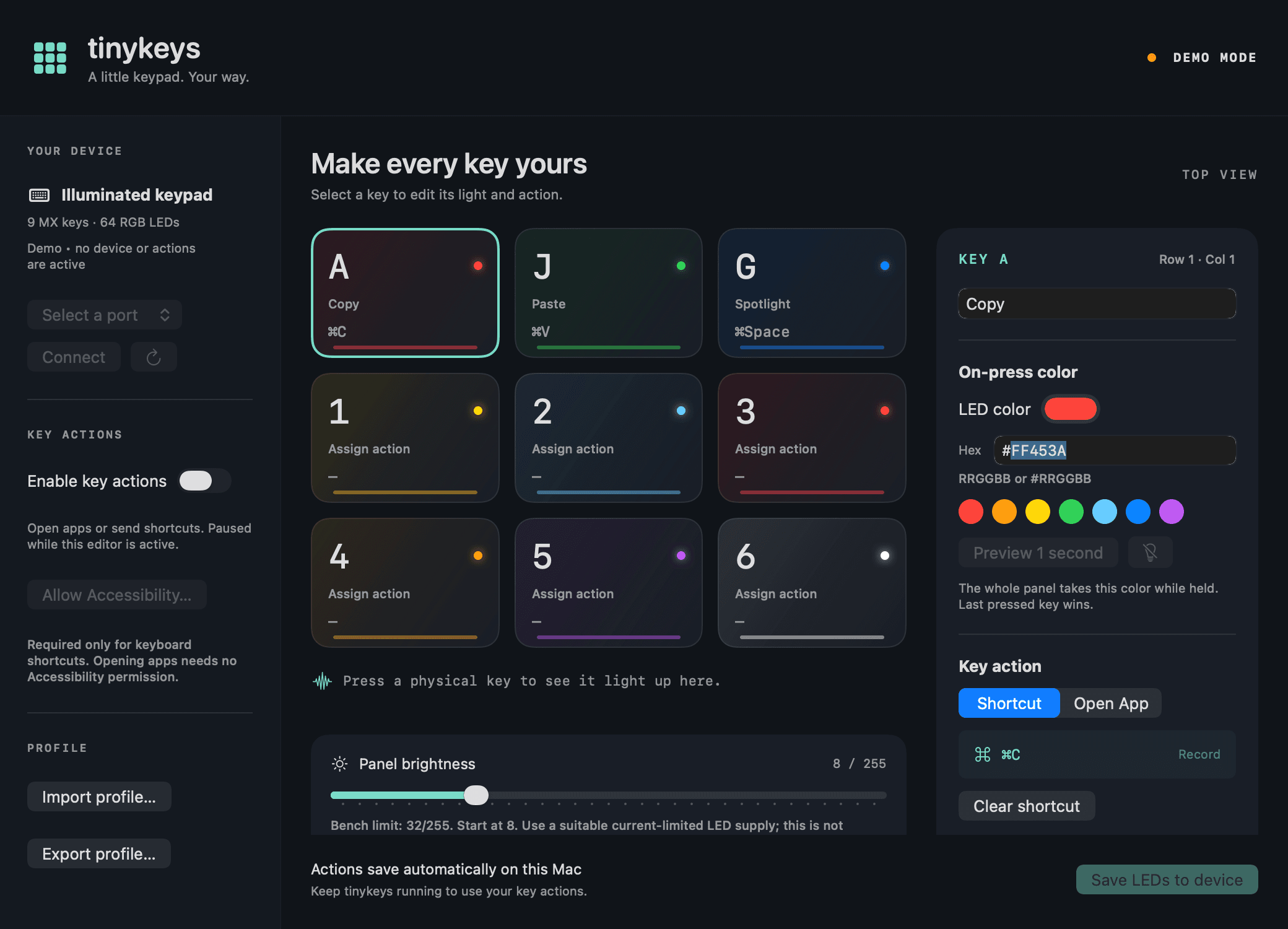
Configuration editor in offline demo mode.
Select a key to set its color and assign either Shortcut or Open App. Enable key actions, then switch away from the editor to use the physical keypad. Actions pause while configuring assignments so shortcut recording does not also execute them.
| Behavior | Contract |
|---|---|
| Keyboard shortcuts | Require macOS Accessibility permission |
| App launches | Do not require Accessibility permission |
| Action assignments | Save automatically on the Mac |
| Colors and brightness | Persist on the controller after Save LEDs to device |
| Window closed | App continues running in the menu bar |
| App quit | Host actions stop |
| App relaunched | Key actions must be enabled again |
Assembly and validation
- Print and check the test keycap and corner piece, then print the complete enclosure and caps.
- Seat the switches, solder the matrix and diodes, and connect the controller, level shifter, and panel.
- With power disconnected, inspect diode and capacitor polarity, check for shorts, and verify the common ground and separate 5 V rails.
- Keep the case open. Upload firmware, apply LED power before sending data, and connect the Mac app.
- Complete the functional checks below before closing the enclosure.
- Fit the XIAO at the front opening and verify clearance with the actual USB cable. Seat the panel, route wires clear of the screws, lower the plate, and tighten lightly. Fit the caps and check full key travel.
| Check | Expected result |
|---|---|
| Press and release every key | Correct key event; one logical press per physical press |
| Hold multiple keys | No phantom keys; most recently pressed key controls the panel color |
| Release all keys | Panel turns off |
| Assign an app launch | Assigned app opens with key actions enabled and the editor unfocused |
| Assign a shortcut | Assigned shortcut runs with Accessibility permission granted |
| Save LEDs and power-cycle | Saved colors and brightness persist |
| Close the editor window | Assigned actions continue through the menu bar app |
| Quit and relaunch the app | Actions resume after reconnecting and enabling key actions |
| Check the assembled enclosure | USB cable fits; wires clear screws; every key travels fully without rubbing |